

CAE Analysis of Structural Strength and Fatigue
With profound engineering experience and comprehensive solutions in the fatigue and durability CAE simulation analysis, TS Engineering provides vehicle enterprise with the consulting services in the fatigue durability CAE simulation analysis.
|
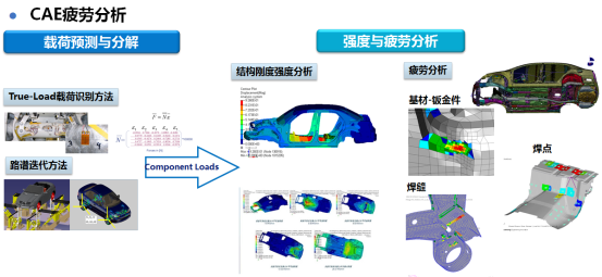
CAE fatigue analysis |
|||
|
Load prediction and decomposition |
Strength and fatigue analysis |
||
|
True-Load load identification method |
Structural stiffness and strength analysis |
Fatigue analysis |
|
|
Road spectrum iteration |
|
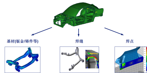
Base material (sheet metal/casting) Welding seam Welding spot |
|
3.1 Load prediction and decomposition
Obtaining accurate component load is the premise and key to fatigue analysis. The TS Fatigue Durability team uses a variety of advanced load prediction methods to obtain accurate component loads, including:
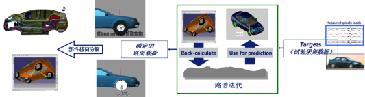
§ Road spectrum iteration method
The multi-body dynamics model is widely used in the fatigue load decomposition, and the road load is decomposed into components such as body and chassis.
|
Component load analysis |
Defined pavement load |
Road spectrum iteration |
Acquired data test |
Based on the multi-body dynamic model and the road spectrum virtual iteration method, the load prediction and decomposition of the vehicle multi-body dynamic model without constraints are conducted.
w Avoid using tyre and road models.
w Based on the test of previous generation vehicle or reference vehicle , a reliable road spectrum for the development of new models can be calculated.
w Overcome the limitations of direct application of six component calculations.
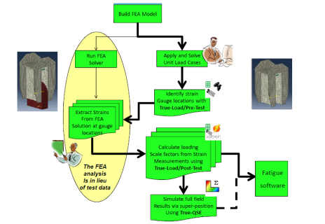
§ True-Load load identification method
True-Load load identification method is a load reverse identification technique based on strain test,which is more accurate and efficient than the traditional strain load identification technology, combining the finite element model and the actual structural strain test, and using the finite element model to support the development of strain test scheme and strain calibration.
The process of True-Load load identification method is as follows,
w The finite element model is established to ensure the accuracy of the model and control the unit type and quality.
w Based on True - load, the finite element model is used for Pre - Study to help study and formulate the strain gauge layout scheme.
w Formulate the strain gauge layout scheme, data acquisition scheme and the test plan under the actual use environment.
w After the strain gauge is mounted on the structure, the components with strain gauges will be fixed onto the vehicle.
w In practical use environment, strain tests are performed of typical user working conditions.
w The test data are processed and analyzed, and the connection point load of frame is identified based on True-Load.
w Based on the identification of the connection point load, the load boundary conditions corresponding to the user's working condition are established.
3.2 CAE analysis of structural strength and fatigue
For the development of vehicle fatigue and durability, TS Engineering provides the following complete CAE analysis solutions of structural strength, stiffness and durability.
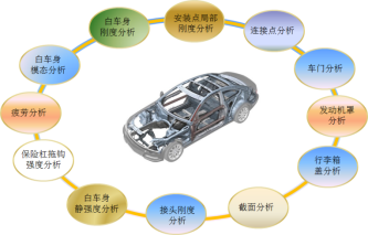
l Structural strength and stiffness analysis
w Analysis of BIW modality, stiffness and static strength
w Local stiffness and strength analysis of installation point
w Connection point analysis
w Joint stiffness analysis
w Static strength and stiffness analysis of chassis components
w Vehicle door analysis:Torsional stiffness, hinge strength, stiffness of the outer plate, deformation of the seal, self weight drop, lateral stiffness of the door frame, stiffness of the inner plate and rigidity of the waistline
w Engine cover analysis:torsional stiffness, sag stiffness, drop deformation, installation deformation, and palm indentation
w Trunk cover analysis:analysis of torsion stiffness, external plate indentation stiffness, outer plate dent and sealing force
w Strength analysis of engine mounting bracket
w Strength analysis of prop shaft bracket
w Strength analysis of battery support
w Strength analysis of ESP bracket
w Strength analysis of bumper decoupling
w ……
|
BIW modality analysis |
BIW stiffness analysis |
Local stiffness analysis of installation point |
Connecting point analysis |
|
Fatigue analysis |
Strength analysis of bumper towing hook |
Vehicle door analysis |
Engine hood analysis |
|
BIW static strength analysis |
Joint stiffness analysis |
Section analysis |
Trunk cover analysis |
l Structural durability
w Structure fatigue analysis of body and subframe:Based on the component load obtained by load decomposition, fatigue analysis is conducted by high cycle or low cycle methods, including sheet metals, solder joints and welds
w Fatigue analysis of the chassis structure
w Closure durability: door closure fatigue, engine hood, trunk lid, etc.
w Fatigue analysis of wiper support
w Fatigue analysis of ESP installation support
w Fatigue analysis of engine mounting bracket
w ……
|
Base material (sheet metal/casting) |
Welding seam |
Welding spot |

CAE analysis of structural strength and fatigue
